So, the other day I went for a ride and found that my headlight wasn't working (I was on a short ride). I tried high beam and it was, so I thought "blown bulb" however ... it was then I noticed that my neutral light was very dim and that the indicators were not working properly (not blinking).
After I got home I pulled the headlight off and checked the bulb.
All was fine, which wasn't a relief, because now I had to find what the problem really was. I lifted the seat and found that a fuse (was blown).
Now its worth revisiting the bike and note that its not "original". As you can see below the airbox is missing and you can make out a tray under the seat which holds most of the electricals:
Including the slim battery:
which (importantly) has a "quick plug" type connection with a built in main fuse (of the blade type).
It was rated at 15A and I noted (in the manual) that the main fuse should be a 20A. I replaced the fuse then I checked wires to look for some sort of short (wire rubbing against inside of the metal bucket is a candidate) and all appears fine.
This leaves me with 2 questions:
what caused the fuse to blow
how then (with the fuse being blown) was my high beam getting power?
So I pulled the fuse and put my Multimeter (set to Amps and it reads up to 10) in across its place to see when current was flowing and began looking for problems. I quickly found that the headlight worked sometimes, but with a bit of movement went off and the meter rapidly climbed. I'd then turn off the light and resume after "moving it till it was ok again".
It took me a couple of days (no more than 4 hours each session) to work out that it was actually the loom rubbing against the steel of the bike ... look carefully at the picture below, you can see the loom resting against the steel of the headlight bracket.
I became confident this was the issue because when I relieved this pressure / contact (lifting up) the much higher power drain went away and the headlight operated normally.
I looked around and found some things worth observing:
1. weight pulling down on the harness from the cable
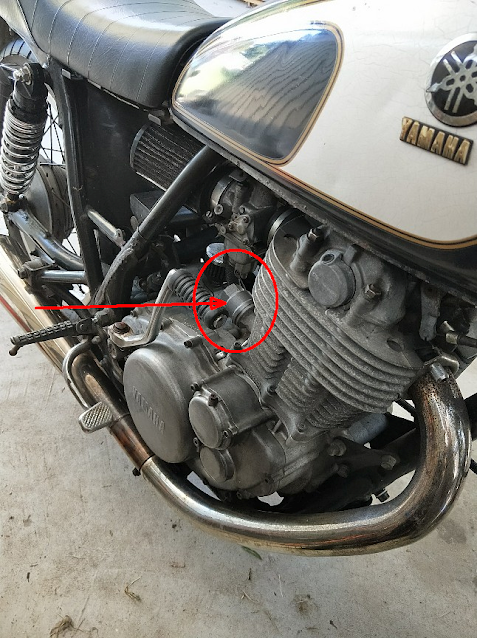
The loom ran under the cable for the exhaust valve decomression cable and
2.
The loom ran under a bracket which supports the tank from wobble. I thought perhaps if this was lifted up it would free the loom from fouling the bracket and consulted the manual:
ahhh hah ... so somehow this had been put together wrong some time back (probably 2016 when it was imported into Australia).
So I re-ran the cable back under the loom and ran the cable over the support:
which then lifted the loom away from that cable seen here:
which you can see elevated it and also took the weight off by running that cable for the exhaust decompression to under where the loom goes , this now relieved the headlight support bracket rubbing point.
3. I also "splinted" with some plastic (cut a section from a 2L milk bottle), some duct tape and a cable tie (which should also prevent it pulling out of that if it feels so inclined).
So, its now been test ridden and seems to be doing ok ...
I fully appreciate that there will be some copper getting atmosphere in there now, which is less than ideal, but to do that job I'd have to strip back even more than I did as well as undo the loom searching for the wire, cutting and joining in a new piece and putting it all back together (probably adding several hours).
I've had this Sunbeam coffee maker since about 2004 and I paid about AU$100 for it when the Baby Gaggia was about $600
The unit dimensions (in cm) are: 31 high, 17 wide and 28 deep (front to back)
A good friend of mine had the Gaggia Classic and I wasn't sure I wanted to commit that much money (I was again a student at the time) and the Sunbeam appealed to me on the basis of price and benchtop footprint. I've always managed to have cramped kitchens. Indeed it features in this 2014 (whimsical comic) video I made when I was living in Finland and again you can see there was limited space on the benchtop.
So, yes, its been between Australia and Finland and back to Australia (more than once).
Basically its a single boiler system which is NOT a Termoblock (also something I don't really like), like so many machines in this pricepoint they have one of those baskets designed for noobs (or morons) which has a closed in base with a pinpoint hole to:
provide emulsification of the oils to make a faux crema (to make the incompetent feel good immediately)
give some back pressure for the pump to ensure flow rates and extraction with improper grinds (again, to make the incompetent feel good)
Being the guy I am (check out the DIY tag as well as the coffee tag for posts) I immediately took out my angle grinder and carefully opened that base up ...
which requires some of that outside be left around the edges of the base to be a support for what is essentially a pressed in mesh
I could have opened it up a wee bit more, but its sufficiently open (more than 90% open) now.
A weakness of the system is that the water from the top shower (more like a dome above the basket, which seals on the flat part of that basket rim) isn't so perfect in water distribution and so the system benefits from a nice (51mm) insert that lays atop the coffee and sits perfectly inside the basket
This has been such a great improvement to my shot consistency (which I've only had for a little over a year now).
The controls are quite rudimentary and if you are a noob (which sadly is who this machine is aimed at) you can stuff things up (perhaps not as much as you can with a Gaggia though).
the bottom switch turns the unit on and begins heating the boiler
the top switch starts the pump and you have to turn it off manually (just like the Gaggia)
However the "saving grace" of this system is that to activate the boiler you have to turn the steamer dial where a "cam" presses down on a microswitch inside to activate the "other heating circuit" to get steam up to pressure.
The upside of this is that unlike the Gaggia you can't accidentally have the boiler at well over 100°C and essentially "cook" your brew ... the downside is that it spits a little water for a bit as it starts to steam. I put a cup under it and you can learn to judge when's a good time to start steaming this way too (if you are the kind of person who learns by doing). Turning off the steam therefore also turns off the steamer circuit.
The machine doesn't power down, so (like the Gaggia) you'll have to remember to turn off the power.
With the lid off you can see the wiring and the two thermostats for the different temperature control (water vs steam).
Frankly, for the money I think manufacture is simple and effective. That its lasted 22 years and been moved around a lot is a testimony to its reliability.
Milk steaming is in my opinion among the best and no extra work is needed to have a good simple chomed metal steam wand straight from the Get Go (unlike say the DeLongi ECP3630 which is perhaps the modern version of this design)
indeed the end unscrews easily for cleaning (should you happen to clog it by not clearing / cleaning it after use)
it even comes with a pair of cleaners (one small one for the little hole which I cut off the base of the basket anyway) that are under the lid of the removable water tank.
That about rounds up the machine.
Tips
I'll say that I think its important to always use filtered water (meaning filtration for ION's like Calcium) out of the water because that will destroy the boiler more quickly. Depending on your city or town water there can be a lot of ions in the water, so invest in a filter jug (I used a Britex, but no in Finland where water quality seemed excellent).
For those who want to get a bit more advanced in operation; you can actually have some "blunt" control over the water temperature that flows out of the group set. I find this important because in my dial in process with my beans I felt that my water temperature was a bit cool. Claude suggested:
and while its hard to measure (because a very fine, light weight, sensitive and accurate thermometer needs to be used and the temperature will change as fresh colder water comes into the boiler), I believe mine is under that 93 mark. So I wanted to raise this a little.
My method goes like this and has the assumption that water boils quite reliably at 100C. Here, my altitude, is about 500m. Again I'll turn to Claude for a nicely formatted summary (of something I doubt is contentious)
I've confirmed this with my own (pretty decent, laboratory grade thermometer) and its quite close and begins sinking fairly quickly when you take the power away.
To get my boiler up to 98 I can just turn on the the boiler again by opening the steamer knob just enough to hear the boiler begin to operate. By running it till water is just beginning to sputter out of the spout I know I've pretty much got to boiling (and it won't go past that point quickly with the boiler open).
I now turn off the knob (make sure its a bit firm or the pump will cause water to push out the steamer wand) and start the pump (obviously the handle / group set is attached through all this).
By getting a sense of how long (I used my phone's stop watch) it takes for the low roar of the boiler to start and spitting to begin, I can make an estimation of temperature because it will rise in a fairly linear manner.
This has made a great improvement to my medium roast coffee. I've since found others are doing this (so in case its not as obvious to the Noobs as it was to a chemistry and electronics guy) Tom calls it Temperature surfing:
He doesn't have a video on modifying the basket in the group set but there was no "easy purchase" option for me 15 years ago.
From here its about you, your taste, your grinder and your beans. I keep notes about my beans and what grind works for each, as its different.
Plenty of good discussions on the internet about this, but I happen to have a fair amount of time for what James says:
So remember the size (depth as well as diameter) of the basket and have a go at this video
Myself I find that 19g is about as much as I can get into my basket (and I've made a simple tool to achieve that in my grinder).
its literally as simple as bit of grease proof paper that I've cut into a cuff that stands sufficiently above the rim of the basket. I just tap that down (by hand) then on the bench gently remove the paper cuff (pulling it up) while giving the the whole thing a quick "tap" back down on the bench to make the coffee settle into that small gap between "where the paper was" before you pulled it up. Note the small black dot, this and one on the other end shows the overlap so I can grab that and the other side and pull up keeping its shape ...
Importantly my grinder has a dial that allows me to adjust how long it grinds for, and its (electronically) linked to the grind size, (somewhat) and reports numbers on the digital display for both grind and time. This means I can repeatably get a dose as I change between beans.
Then have a watch of this video and see what you think. Ultimately start practicing, take notes and enjoy your coffee journey
There you have it, a great machine which I can honestly say "they don't make them like this anymore" for that price point.
I hope that this review even if you get something like a Delongi (a great machine too) and begin modifying that to help you get good quality coffee at home for yourself.
So my dash let me know that it was CVT belt inspection time again and so I pulled the covers off and then removed the front (half of the front) sheave to have a look. This setup has been in place for quite a while as this (link) was my last belt and CVT rebuild. I strongly recommend that you go read that too (if you haven't already) as that contains a bunch of other helpful information too.
note the bolts inserted into the rear (secondary) sheave to "de-tension the spring" which is a needed thing if you haven't done this before and don't have a manual.
Belt looked good but I didn't waste any time gazing at it in situ because my first quick measurement of it showed it was close to tolerance.
So I put it flat on the bench and sure enough, it was close...
and so yep it was getting changed.
The astute may have noticed a crack in the belt between the callipers and so that is something that I'd be keeping an eye on anyway ... Indeed this belt has been on this bike since the above mentioned service and that was at about 100,000km on the bike Odo (actually I'm thinking more like 95,000 but meh).
So with now 162,332 on it I've replaced the belt and rebuilt the CVT with new weights. 100,000km on the belt and same weights, that's not bad (and I'd like to see you get that out of a chain and sprockets).
The Yamaha inspection interval is built into the dash (and you have to reset it when the service is done) at 20,000. This means I've done four prior inspections on this thing including this "inspection" at 130,000(ish)km for replacing a sealon the big end bearing. Everything was within spec so it all went back in. Now the guidance from the 2002 model was to "inspect" the belt but that changed in the 2007 manual to "replace" ... I'll assume this is because of inadequate skills in inspecting staff or just that at $100 it wasn't worth their while even inspecting.
The weights
But I always disassemble the sheave, inspect everything; replace as needed.
as you can see, some of the roller weights were starting to show flat spots, this is bad because then they become sliders, and that's another company. The sliding effect is not what was desired by the designers (although an after market one does this) who wanted those weights to roll (or at least I expect that was what they wanted). Once a flat spot has started then it is going to pretty much get stuck in that spot ...
...as it will get "caught" on that by the pressure of rolling past the lower height. This is bad for a number of reasons (not least will be uneven pressure on the sheave parts).
This seems like a good time to go back to the last time I did this (here). On that occasion I found that:
... except when I weighed them (on a scale that is only reading in grams) I found they were some 18g and some 17g ... when I weighed the bunch they were 143g (or 17.8g on average).
... Interestingly the Yamana ones were on average 19.37g (or 155g for the lot) which as a whole mass acting on the variator is about 12g heavier ... which will mean that it takes a higher RPM for the mass of these to overcome the spring (in the secondary sheave) and mean a higher RPM before the "front" is fully engaged..
This is something to think about so lets look at what the ones which I put in then weigh and what the ones I bought to replace them weigh:
During weighing the (now) old weights I had a few strange situations so I reweighed a second time. Interestingly the sum of all weights was basically identical and the new weights are very close to what the ones I'm replacing now started out as.
Shouldn't be too surprising when you consider the shavings apparent in the sheave side. Also the new roller weights are now a different material than earlier, and aren't as dark, which I hope means they'll be somehow improved.
I don't know what the material is but I expect that its a polyurethane. I was tempted to rub some graphite into the surface to perhaps help with "sliding" but I read that there is an interaction between graphite and polyurethane as Google AI suggests:
Yes, graphite physically interacts with polyurethane when used as a filler to form a composite material, which modifies the polyurethane's physical properties. There is generally no significant chemical reaction between the two in standard preparations, but strong physical interactions (like adhesion and hydrogen bonding) are formed.
so I left it off for this first operation ... I'll inspect and report at the next 20,000 inspection.
So with it all cleaned
I lubed the interior of the shaft and the nut and assembled it.
torquing the nut on to the correct amount. The tool I have works nicely by just using the bike's weight and the lever of the arm onto the ground to hold the crank (cos that's what the nut is on) steady while you apply the right (160Nm) torque.
At this point I always start it and check that it operates well before I put the covers back on.
Oh, and I replaced the air filter that's over the rear sheave air intake ...
We (mostly) all know that as things age they stop performing at peak levels, sometimes replacement is the best solution, but perhaps other times intervention can fix the issue. I'm not one to shy away from a surgical intervention if needed, but if another therapy can work then all the better.
Background
So, while the WW was going well these last few years I've been using it less (favouring my bicycle for shorter trips in and out of town) and its had a few small issues that I've needed to fix (like the seized rear motor, exacerbating the not using it as much).
I noticed however that the battery was "sagging down" more in voltage sooner than I thought it should do as I was riding (you know, that volt meter on the handlebars does have a useful purpose right?) and began thinking that it may be something more than just expectable aging.
I always check the "Watt Hours" (Wh) shown on my charge monitoring tool (that always remains plugged in between the charger and the scooter), and the Watts needed to recharge are less than what I'd have expected were the battery depleted down to that level of "remaining charge" (as represented by the voltage when riding). For reference, this is the Watt meter I use:
It conveniently shows how many Amps are flowing, the battery Voltage and on the bottom row cycles the left number through
Amp hours (Ah)
Watt hours (Wh)
Peak Amps (Ap)
Voltage maximum (Vmax)
Peak Watts (Wp)
the right number shows just the current situation of Watts flowing. Its a great tool and I would strongly recommend everyone with an eScooter or an eBike have one of these; you learn a lot from them.
I mean unless you're stupid, then you don't learn anything ....
First step
So I decided to pay attention to the last part of the charging cycles and come on in at the end; glancing at it as I went about my doings around the house.
I noticed that it was 0.18A (that's also 180mA) at one point, then suddenly became 0.00A ... that's wrong as before I've seen it taper nicely down to 0.01 Amps (because I like to watch these things, just like I like to watch the food I'm cooking so I don't burn it).
"Riigghhhttt" I thought, "the BMS is cutting off before balance has completed" ... first step was to turn off the charger (at the wall, in Australia power points have switches on them) and leave it plugged into the charger (so I can monitor the actual charging point voltage as well as the "take off end" that shows on the handlebar, yes they are different voltages) and wait a while (about half an hour) and then turned it back on ...
bam ... started charging at 0.56A and I thought yep, diagnosis looks right: BMS is shutting down, the full cells settle (after charging) lowering the difference between pack cell groups. The role of the BMS (among other things like discharge protection) is to ensure that charging is stopped before any cell (bundle) is over charged (think fire risk) and to help fully charged cells bleed over to the less charged cells (although different BMS's do this with different levels of quality).
So clearly it was shutting off before the other cells were fully bled.
Not wanting to stand there all day I decided to automate this with a simple "clock work" power timer I had lying around ...
I set it to provide power for 15 minutes and not provide power for 15 min. I can "turn it on" for the first bulk charge (to save time) using the switch on the side:
in the up position its providing full time power (ignoring the settings) and in the down (blue/green arrow) position its on the timer.
Lastly
I've put together this quick video showing all this and discussing the same points above but in a slightly different angle.
I just thought I'd make a post about how my "system" of the combination of
Solar Floor heating
Insulation in floor and Ceiling
Use of Reverse Cycle AirCon
Wood burning stove
is working out for me.
With overnight lows of about -1C (so frosts) but typically sunny days of about 18C, I get sufficient energy from that to heat the floor and this therefore takes a significant load off the AC because as the floor (basically) never gets heated by the warm air blowing out of that (so, upper walls and ceiling are heated) the floor heating system then brings the whole house up warmer.
This is a typical winter day here:
The time zone indicated by A is where I turn on the R-C A-C and the zone indicated by B is where I lit the fire. Because the house is already warm (and insulated top and bottom) the fire requires just a fraction of what would be needed otherwise.
As the sun starts to warm outside I choose that time to then turn on the AC because the exterior heat exchanger will have more advantage in raising the temperature inside if the outside is actually warmer.
Its just like the height difference between two points on a hill. The higher the difference the more energy you need. So even though I'm using technology and electricity to move and amplify that heat I'm still taking advantage of the Sun to do that.
So only one component would simply not work, but all four parts work together, consequentially my house is warmed (but not 100% of the time, my power bill is much lower) and I burn less than a quarter of the wood. For example the load of wood I bought in 2023 is still serving and I anticipate that it will provide for this winter entirely too.
I'm a big fan of
understanding diminishing returns
seeking maximum value for money
I know what it would cost to improve this situation, and so I'm quite satisfied with the additional amenity provided by my existing solar floor heating in conjunction with Reverse Cycle Air-Con and insulation to augment the little wood burning furnace that the house already had delay the need to and reduce how much I burn when I do.
I decided that I wanted to change the (rather antique style) grips on my SR500 for something more comfortable.
I'm pretty happy with them but unlike the older styles, the ends are "uncovered" on modern grips. This left me the task of attaching end covers for aesthetic and functional reasons. I ended up selecting these:
as (before I'd taken the grips off) I figured they'd be suitable no matter what I found (empty hollow bar end or filled in with something. As it turns out the Yamaha bars had solid steel rod inserted into the bar to assist with damping vibrations. So I had to drill and tap a thread into this.
This task was done by:
carefully identifying the center and then marking that with a center punch
drilling a small pilot hole (that was straight and con-centric to the bars)
successively drilling this out to the final diameter needed for the thread cutting tool
cutting that thread (there's a technique)
shortening the supplied bolt
screwing it in and using light grade thread locker on that
Left hand done, I moved over to the right where I met with problems on step 4
Because of an additional complication on the RHS, you can't imagine how much I feared this outcome and had taken every possible precaution against it by
turning gently (two fingers)
only turning till it bound
back off at least one, sometimes two turns to feel for the 'break' of the cutting tool swarf
backing all the way out to double check the measurements of drill depth
knowing how far I'd been able to turn the cutting tool into the newly cut thread...
Of course now I haven't fucking got a cover on that side because when you break these off in there, there's just no drilling it out ...
On the place it broke, I'd felt that while the screws had enough thread I did not test that on the many occasions I'd backed out. I should have been doing this to be clear exactly how many turns of thread the cover mounting screw had (and it only needs a few right!!).
Had I done that I may well have saved this issue, had a good looking bar end on the right and maybe just more loctite on that one ... FCK
This is as much a warning to others as an exercise in accident analysis and self punishment
Sometimes things go as they should, and sometimes they don't; when they don't it can be an opportunity to learn more.
I recently did an oil change and it seemed a good opportunity to check my SR500's timing chain tension. Its actually incredibly simple to do and quite accessible right there on the right hand side of the bike.
I usually call it Cam chain and my old manual does too.
So normally one just undoes the (27mm, and the standard toolkit has exactly the right spanner for this task - yeah \o/ ) cover cap (the thing visible here)
and access the locknut beneath:
However in my case when I removed the cap I found this:
which was a bit perplexing ... please note rag and small amount of oil on rag. You need to take this into account when you remove this cap to reduce clean up.
However a quick look at the cap revealed the issue:
yep, the locknut had come 'loose' from the body and simply unscrewed with the cap ... (facepalm).
It undid with just my finger.
Note carefully that O-Ring that's in the cap ... it can fall out unnoticed and must be in there when the cap is put back on ...
So, with the adjuster bare (no need to do this yourself) its a good time to talk about what we are doing.
Our goal here is to adjust that so that the inner pin is flush with the outter surface of the adnuster nut so, you need to use a 10mm spanner (also in the kit) and (probably) screw it in.
The process of determining this I used is to turn the motor over (with the ignition turned off and the decompression lever pulled in) using the kick starter by hand while looking at that (apparently a screw) in the center. You want to turn the motor over looking at it in various positions (perhaps starting from Top Dead Center, for which I just used the white mark visible through the window) as well as other places.
Here you can see its actually lower than the outer part of the nut (and I watched it during the turn over). So in my case I adjusted that in.
Screw the nut in untill the surfaces are flush (which is actually a cast piece of a longer component that looks like this):
its perhaps not clear in that where the adjuster is, but careful thinking about it will reveal it all. This is from an SR400 manual btw.
Perhaps turn it over again observing that it moves in and out a little. So then with that done just put it all back together, tighten to specified torques (or just firm but don't try to strip threads) and you're done.
Below is the advice I got from a friend before doing this (*thanks Stu)
Dead simple... all I do is
* put the engine in TDC on compression
* remove the spark plug
* take it a bit past the T mark then roll it back to the T mark again
* undo the tensioner cap (angle the cap down as you remove it to catch the oil, stick a rag under the area anyway)
* loosen the big lock nut a bit so you can adjust the 10mm centre nut
* carefully screw the centre adjuster in 'till the slotted plunger comes almost level with the end of the adjuster (it's not a screw and don't try to force the adjuster with the 10mm)
* then rotate the flywheel back and forward a bit to ensure the centre plunger moves in and out slightly
* screw the lock nut back up then holding the adjuster with a 10mm spanner lightly, tighten the big lock nut.
* Change the O ring if you feel so inclined, tighten the cap a bit then all done!
I hope this demystifies the process for any "wrenching beginners".
Best of luck with what seems harder (before you've done it) than it is.


.jpg)