Showing posts with label T-Max. Show all posts

Sunday, 23 November 2025

CVT rebuild time (again)

So my dash let me know that it was CVT belt inspection time again and so I pulled the covers off and then removed the front (half of the front) sheave to have a look. This setup has been in place for quite a while as this (link) was my last belt and CVT rebuild. I strongly recommend that you go read that too (if you haven't already) as that contains a bunch of other helpful information too.


note the bolts inserted into the rear  (secondary) sheave to "de-tension the spring" which is a needed thing if you haven't done this before and don't have a manual.

Belt looked good but I didn't waste any time gazing at it in situ because my first quick measurement of it showed it was close to tolerance.


So I put it flat on the bench and sure enough, it was close...


and so yep it was getting changed.

The astute may have noticed a crack in the belt between the callipers and so that is something that I'd be keeping an eye on anyway ... Indeed this belt has been on this bike since the above mentioned service and that was at about 100,000km on the bike Odo (actually I'm thinking more like 95,000 but meh).

So with now 162,332 on it I've replaced the belt and rebuilt the CVT with new weights. 100,000km on the belt and same weights, that's not bad (and I'd like to see you get that out of a chain and sprockets).

The Yamaha inspection interval is built into the dash (and you have to reset it when the service is done) at 20,000. This means I've done four prior inspections on this thing including this "inspection" at 130,000(ish)km for replacing a sealon the big end bearing. Everything was within spec so it all went back in. Now the guidance from the 2002 model was to "inspect" the belt but that changed in the 2007 manual to "replace" ... I'll assume this is because of inadequate skills in inspecting staff or just that at $100 it wasn't worth their while even inspecting. 

The weights

But I always disassemble the sheave, inspect everything; replace as needed. 


as you can see, some of the roller weights were starting to show flat spots, this is bad because then they become sliders, and that's another company. The sliding effect is not what was desired by the designers (although an after market one does this) who wanted those weights to roll (or at least I expect that was what they wanted). Once a flat spot has started then it is going to pretty much get stuck in that spot ...


...as it will  get "caught" on that by the pressure of rolling past the lower height. This is bad for a number of reasons (not least will be uneven pressure on the sheave parts). 

This seems like a good time to go back to the last time I did this (here). On that occasion I found that:
 
... except when I weighed them (on a scale that is only reading in grams) I found they were some 18g and some 17g ... when I weighed the bunch they were 143g (or 17.8g on average).
... Interestingly the Yamana ones were on average 19.37g (or 155g for the lot) which as a whole mass acting on the variator is about 12g heavier ... which will mean that it takes a higher RPM for the mass of these to overcome the spring (in the secondary sheave) and mean a higher RPM before the "front" is fully engaged..

This is something to think about so lets look at what the ones which I put in then weigh and what the ones I bought to replace them weigh:


During weighing the (now) old weights I had a few strange situations so I reweighed a second time. Interestingly the sum of all weights was basically identical and the new weights are very close to what the ones I'm replacing now started out as. 

Shouldn't be too surprising when you consider the shavings apparent in the sheave side. Also the new roller weights are now a different material than earlier, and aren't as dark, which I hope means they'll be somehow improved.


I don't know what the material is but I expect that its a polyurethane. I was tempted to rub some graphite into the surface to perhaps help with "sliding" but I read that there is an interaction between graphite and polyurethane as Google AI suggests:

Yes, graphite physically interacts with polyurethane when used as a filler to form a composite material, which modifies the polyurethane's physical properties. There is generally no significant chemical reaction between the two in standard preparations, but strong physical interactions (like adhesion and hydrogen bonding) are formed. 


 so I left it off for this first operation ... I'll inspect and report at the next 20,000 inspection.

So with it all cleaned 


I lubed the interior of the shaft and the nut and assembled it.


torquing the nut on  to the correct amount. The tool I have works nicely by just using the bike's weight and the lever of the arm onto the ground to hold the crank (cos that's what the nut is on) steady while you apply the right (160Nm) torque.


At this point I always start it and check that it operates well before I put the covers back on.

Oh, and I replaced the air filter that's over the rear sheave air intake ... 

Job done

Thursday, 25 January 2024

Cheap-o regulator rectifier

Given how hard it is to get a regulator rectifier for an old bike (I'm probably going to be waiting 6 more weeks), I thought I'd add a little more to my analysis yesterday (see here) of the failure.

The problem was clearly thermal run-away and (not yet) that of the thermal paste (which isn't used anything like properly). So lets start with what the regulator rectifier looked like on extraction from the bike.


The bulge and the spatters of metal (yes, metal) indicate high temperatures (to melt the metal).

So I cut the arse of it off and chiselled it out.


Which shows that there was still some thermal paste, but also that there was not a good physical connection to the metal of the heat sink (because its quite rough looking, ideally it should be polished smooth. So that's manufacturing failure #1

Next we flip that black box over and see that its easy to split (its already fractured)


and we can see the guts ... of course the board is burned down to glass fibers in places. Not only is the heat escape pathway interesting, but what the fcuk are these little chunks of white rock doing in here?


you can see that the not only are the components toast, but we can see the legs of the coponents are totally gone too


This would explain the tiny spatters of molten metal above.

Lastly the thing stinks, probably due to the boiling of the organic solvents used in the (copiously applied) thermal paste.

On this point I'm going to say that cheap thermal paste that uses organic solvents, when applied like a kids use of toothpaste is a recipe for disaster longer term. This is because any significant heat (say, over 50C) is likely to see the loss of this material over time; weakening the effectiveness of the transfer of heat from components to outer case.

So if I was you, as well as making sure it stays cooler (as I examined in the previous post)  I'd be replacing these things pre-preemptively after every few tens of thousand hours (roughly equal to kilometers) or per few years on bikes that don't get used much. Especially if you use your bike on hot days (like Australia, California or other hot dry places).

HTH

Tuesday, 23 January 2024

T-Max cheapo regulator rectifier

So, it happened again...

My nose identified the smell of burning insulation and electrolyte, and I noted some smoke emerging from "down there".

I quickly pulled off the road (smoke being spread by the fan) shut off the ignition, pulled the tool kit and disconnected the battery.


This left me on the side of the road, so I pushed it down a lane a little ways (to keep it from attracting the wrong kind of attention), hitch hiked home (I was on the way home), got my truck and came back with a new part and tools.

It requires a bit of jiggery to organise me getting back both vehicles.

Readers of my blog will know of my previous issue (documented here) and my conjecture of would it survive the hottest days ... I'm pretty sure I know the answer now ;-)

As I wrote back then when I fitted the fan unit:

I was riding around and thinking about how close that graph got to 50C and thought that since the air temperature right now is like 20C (middle of the day) and that in summer its going to be nearly 50C (coming directly off the road) that will drive that temperature up closer to limits again. So I decided to look for power and attach a small case fan to assist cooling.

So as I suspected on at +34C day it didn't get sufficient cooling.

I decided that I needed to do new testing (because it was still bloody hot) and so I thought test it with

  • cover on (fan cooled only)
  • cover off (fan still there)

To test I embedded a sensor between fins to avoid air cooling of the sensor (and get the temperature of the heatsink) like this:


*(Note: the new cheapo part is no longer black, which is stupid)

The "cover off  ride looks like this


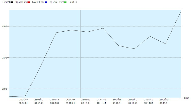
with good exposure to air for the cooling. The temperature plot (which included a length of highway at 100km/h)


which is quite reasonable. You'll note that temperature rose as soon as I returned into 60km/h town region and stopped recording when I pulled into my yard.

I then slipped the cover on 


note the breather which is a vent (see the earlier post) that leads to the center of the fan (and hopefully blows fresh road air in).


and went back out, getting this reading

you'll note that it got to 60 pretty soon and flattened (I was keeping an eye on the meter readout) and rose briefly when I was back in town (presumably due to lower air flows.

This temperature is very close to thermal runaway temperatures and IMO far too warm for a cheap piece of shit like this. This site on that subject makes that clear.

Semiconductor parts are most often specified for use in the “commercial” 0 to 70°C and, to a lesser extent, in the “industrial” -40 to 85°C operating temperature range. These operating temperature ratings generally satisfy the demands of the dominant semiconductor customers in the computer, telecommunications, and consumer electronic industries.

So I've ordered a Yamaha part to test. I want to know if the part that costs $300 is worth its money. Perhaps it may run cooler?

I'll post more when it comes to hand. For now its not being ridden.

Addendum

So, as promised, I took the T-Max into Warwick (37km) on a warm (but not scorching) 29 ~ 30C day (just a few days after this was first written). The results were very interesting. First the full trip


We start off with the surface of the heatsink being 25C, and I let it sit for a little while before starting off. I did the same when I got back. I rode into town, parked at a hardware shop at about 9:40. The temperature of the heat sink started to rise after the air flow stopped (I presume as the hotter parts inside the unit transferred their heat out and it was radiated away).

I then rode to another shop (quite close) which resulted in a quick air cooling and then a smaller rise. I was there until about 10:15, where I started up and rode home.

Lastly, after getting home I let it sit for a bit before shutting off the data recorder.

The trip in. Please note that in this graph I removed temperatures below 20 which does tend to change the actual scale of the graph, it also makes it a bit easier to see. I topped it out at 60C because I feel that's the danger zone.


The trip home.


Again we see that as soon as it is generating heat (by rectifying the AC from the alternator into DC and regulating that and dumping what the battery doesn't require as heat) its also moving, and when its moving slower things heat up faster. You can see when I come into town, slowing down and getting less air cooling.

So next I'd need to test this in traffic ...

I'll keep you posted

Saturday, 22 May 2021

T-Max blowing after market regulator rectifiers (and how to fix it)

One thing that is annoying lately on my (now elderly) 2007 T-Max is how often the Regulator Rectifier is dying. I've had what are significant and expensive problems caused by this in the recent past and even going back years its stood me up in the past too with a previous model.

I believe that the problem is the construction of the after market ones compared to the original ones, right now (in Australia at least) getting genuine ones is "special order ex-Japan" and they are now AU$360 - fark!

So how can I make do with what's available at sub $40 price, which BTW the genuine ones used to be $80).

What happens?

Thermal failure is what seems to happen. When you pull the regulator you can see that its "popped" up at the back (opposite end to the plug).


Wanting to see what was there I worked at prising it open ...


The first thing that stands out is that its got thermal paste (badly applied) to a heat transfer plate to marry it to the sink body ... so that's a step back from the yamaha design because only one side can shed heat. Next you can see that the backing of the heat sink is not polished at all and so will have even greater reduction of heat transfer capacity (and NO thermal past should not be used like tooth paste, it requires a very clean joint and is only to fill tiny imperfections).

Next we can see that the thermal (tooth) paste application has boiled off and sunk down into the bottom of the crevice meaning that the regulator (encased in plastic) can shed even less of the heat.


Meaning that the thermal paste changes to become "thermal insulation" ... this just can't work for long if it gets hot.

Why will it get hot? Well simply put if the generator (three phase AC stator type) puts out more power than the system needs it can only get rid of that excess energy as heat ... so yes, the regulator becomes a little heater shunting the extra power off. This happens at higher RPM much more so than lower RPM (when the stator is generating less power), and I believe that 5000RPM is the threshold for that: meaning that on the highway is when it will pop. 

AND THAT FITS MY EXPERIENCE

Understanding the problem

Looking at one of these things its pretty clear that its intended to be air cooled:


... with fins all over it like that (note the temperature sensor "blu-tak" puttied in there).

However its located under the rear cowling cover ... which essentially prevents any air flow (where it pinches tight just where it joins at the front).


obviously this provides it some weather protectection, but as you can see also prevents it getting air circulation. This overlay shows where things are under the cover.


(Note the masking tape) 

The isn't much air flow possible, which is even more clear when viewed from behind that it sits in a "warm air" bubble of whatever air can leak through from the engine bay...


Sealed in a pocket of warm air from the engine, its heat shedding possibilities are low. This is verified by a quick run with the cowling on and off (recall that temperature sensor??)


So I did a highway short run with the cowling on, came home, took it off (had to unplug the sensor briefly) and took off again and did the same run with the cowling off and air flow around the regulator / rectifier.

That red arrow indicates a temperature which I consider on the threshold of operation before thermal runaway (meaning it pops) is likely.

So how did the original survive? Well I'd say because its actually not only better made but better designed. You see quickly (if you compare them) that the after market one just looks cheap and has a resin back. Resin is not a good conductor. So lets look at the old regulator (old picture I'm afraid, I've already binned it)


See that nice aluminium backing? That means that heat can go out through the back too. So now lets look at where it was mounted...

... and we can see there is not only an area for the metal backing to press against (and shed heat into the frame a bit) but there are signs (discolouration) that its been doing exactly that.

Solutions?

Well if I could be sure that a genuine part for nearly AU$400 would do the job I might be more tempted to give that a go, however my measurement suggest to me that an alternative exists; which is cooling the existing cheapie better. 

Having already established that running without the cover results in a remarkable cooling difference I'm inclined to believe that as long as I can get air in there it will work. So with that in mind I decided to try a little pipe directed ducting

I looked at the overlay diagram I'd made and determined where to drill a hole (the masking tape), and with a hole drill, put in a 24mm hole to take some small flexible ducting


which then comes out on the inside.


where I can then see where it comes out from by using the above overlay technique


Which I sub sequentially tuned it to point more down after this shot. I have found that using my thermal camera that the lower portion of the heatsink generates the most heat. "Tuning" was just bending (its flexible hose right?) and I used a cable tie to hold it down there.

When fitted up to the bike its pretty neat


and I'd say that if you didn't know it was there you would likely not spot it


Lastly I did another run into the next village and did some 6000prm run in a few places (you'll see two spikes in the middle)


which is quite a good result, although not as good as fully open was ...

So for now I'm calling this sufficient but when summer comes I'll need to check that its still safe in temperatures. If it turns out that the 40C days we get bring it too high then I'll consider an option where I cut a section out of the cover and expose the fins directly to outside air.

For now though, this is good enough.


POST SCRIPTUM

I was riding around and thinking about how close that graph got to 50C and thought that since the air temperature right now is like 20C (middle of the day) and that in summer its going to be nearly 50C (coming directly off the road) that will drive that temperature up closer to limits again. So I decided to look for power and attach a small case fan to assist cooling.

See the video for details. Sorry about the mistake in speech, I find it hard to juggle a camera, focus and know what to say on an unscripted quickie. Please find below a video, which may not appear on mobile viewing (because mobile is still shit compared to a desktop experience).

for the screws I used I had to

  1. drill out the holes in the CPU fan I had lying around
  2. bevel the edges with a bevel tool (so that they'd sink in  to look cleaner and have enough depth to bite into the cork
  3. there are no screws at the bottom because there the heatsink "next rail" was too low to support the cork ... I might add some and glue it in place if I feel the need. The fan over hangs on the stand but is vertical when riding so it should be ok (bumps ...).

make sure the cork is in snug (not loose) and apply the hotmelt glue to the join of the edge of the CPU and the tip of a cooling fan. Make sure you do not get overspill which blocks the blades (I have experience using case / cpu fans for a few things). Add a little more on the outside and smear it in with a screwdriver blade as you go. The heatsink will cool and set if faster than the plastic case.

I used both because a synergy of two methods is better than one.

HTH

Saturday, 17 April 2021

T-Max charging circuit woes

I've had my current T-Max for some time now and like many (most?) used bikes it came with a few legacy issues of the previous owners (neglect) and the usual litany of shortcut repairs (just one example). Mostly now I'm just coping with the sort of age related things that one expects over time; she is of course nearly 15 years old now. Most of this has been electrical.

My present issue (I believe now solved) harks back to this "event" in early 2019 with a failure of a wire, which was fixed with a rewire of one connector. For one reason or another I ended up not using the bike much (contract out of town) and used it mainly for weekends. However the rise of COVID-19 saw me working from home in 2020 and using the T-Max more (but mainly for trips into the main town 35km away as I live in a small village).

Now all of this took place over a lengthy period not least because of a toe surgery for some arthritis and hurting my back (meaning I couldn't ride),a lengthy period of rain and parts supply delays.

20:20 Hindsight

Now if I could have my time again I'd have done a more thorough rework of the wires involved and that my friend is why I am writing this to you. Rather than just replace that one connector on the RIGHT HAND SIDE which has 3 white,(which BTW is from the stator and thus carries a higher voltage and more power) a red and a black (so a 5 wire plug) you need to look at the origin of those 3 white wires on THE LEFT HAND SIDE OF THE BIKE; because all that happened was that the next weak link in the chain (on the other end of that wire) simply became the next fail point.

Keep in mind when reading this that the failure by me to fix properly the entire wire run from where the plug comes out of the engine (providing 3 phase power to the regulator rectifier) was the cascade event for all this. Again, that is on the LEFT HAND SIDE.

You have been warned.

The Saga of Failure Begins

The problem with bikes is that they have too much plastic over the things you need to inspect (sort of divorcing people from wanting to inspect as well as fostering a whole generation of useless narcissists who are incapable of fixing anything), had the motorcycle had a simple volt meter on the dash (or even a proper "charging" indicator) I may have picked this up earlier, but alas all I got was an occasional flash of the engine light.

So riding home one afternoon of September 2020 (yes, last year) the bike suddenly stopped, it stank and when I pulled over smoke was billowing from under the seat. Lifting the seat I saw it was coming from the battery ... pulled the tool kit (from where its conveniently placed under the seat) and disconnected the terminals, and extracted the battery


which was smoking and puring sulphur fumes everywhere. I'm fucking glad that this was the 2004-07 model not the newer one because the battery is right up there at the frong under all that tupperware and it would have essentially destroyed all the electrics on the bike (including the engine management system). The battery had been totally fried.


So first order of the day was to try to get it home ... that just took a friendly discussion with the local car mechanic and we trailered it home. 

Step 1

With the scooter home I then needed to replace the battery (in order to attempt to start it). With that in place I tried to start it and as soon as I turned the key I knew that there was a deeper problem because the familiar whir of the fuel pump was not there ... a quick test of the fuel pump (with 12V) showed it to be working (but I'd ordered a spare while testing this) and so I thought about it for a while. 

The other choice was that the engine immobiliser was somehow faulty (and it was somehow) as this works by disabling the fuel pump ... I tweaked to this by the fact that the LED on the dash was not doing its thing, but I could not remember what "normal" was.

Step 2

I pulled out the manual and looked over the circuit and could see that there was. I observed that there was an immobiliser sub circuit:


However I soon discovered that this "system" was deeply tied into the Engine Management System (including fuel injection) and from Yamaha the price for replacement was nearly AU$2000 (because it came with keys, a Key Recogniser and an entire new EMS

Faarrrkkk ... 

Some exploration of the idea revealed that the engine immobiliser circuit seemed to be an integral part of what (the frequenlty fucking idiots) in the trade refer to as "the antennae" circuit (which is found under the key unit, obscured partially by the bulkhead) I wondered if this could be bypased.


a discussion with a mate (also electrically inclined) suggested this possibility


which seemed like the obvious next step for a small outlay.

Success was had and the fuel pump turned when key moved to "ON" and the engine started and ran.

Great stuff so now I could move on to working out why the battery was stuffed.

Step 3

With the engine now running I could test the charging. Wow ... the rectifier was working but the regulator part was broken because at idle it was charging a bit much but at 5000RPM it was totally over charging ... 27V

So, this is now the third new mode of failure I've seen on the regulator rectifier.

Step 4

I called to make an order for another regulator rectifier from Yamaha to find that the price has gone up, in Australia it was now over AU$300 and special order, so I hit up eBay again and bought an aftermarket one from some seller and in due course it arrived and I fitted it and it worked!

The plug however was so fucked (recall the previous butchery) that I decided to re-terminate all the connections with just simple spade connectors.


I used a fully insulated one for the center white (three phase) one because 3 insulated ones wouldn't fit together and they were fully isolated from the others by them being insulated.

I looked around at the LHS of the bike where the 3 white wires from the stator plug into the "harness" and they looked a bit gammy but I measured around the joint and it was all passing through the right voltages. I thought about cutting that plug out and just soldering them together but as I'd started to re-assemble the bike dismissed the idea.

THIS IS WHERE ITS IMPORTANT TO NOTE: if something looks like its failing then it probably is, and probably accelerating in its mode of failure.

So I reassembled the bike and wondered briefly should I go back and fix the rest of the wires. Seemed a hassle so put I back together and began riding it.

...

This period lasted until last weekend when it stood me up again. This time however the failure was more graceful this time.

Next Failure

on the way back home from town (35km away) the speedo and tacho fell to nothing and the LCD display blanked ... the motor was continuing to run normally ... I thought "what is wrong this time" quickly followed by "will it make it home" ...

Nope it shutdown and I coasted to a halt.

Another phone call to a friend with a trailer and bring it back home again to put up on the slab and to another autopsy.

While waiting for my friend (about half an hour) I thought I'd just try the key and see if it started. The lights came on and the fuel pump whirr sounded. I noted on the dash that the ODO was now showing. 46 where the ODO was previously. I looked this up (of course I have the manual on my fucking phone) and it declared it to be: "Power supply to the fuel injection system is not normal".

With high hopes I turned the key and it the starter motor had a go at it but gave up.

Step 5

On getting home I charged the battery and while waiting I pulled the regulator rectifier off and measured the 3 AC phase pins with my diode testing setting on my Multimeter. It was rooted (the usual Open Circuit mode of failure this time), so I've ordered a new one (and I'm still waiting for that to arrive)

Wondering about things I started it and measured the AC phases ... well ... one phase was down AND the plug now looked pretty manky over on the other side (left) of the bike 


It was clear that two wires of the 3 were giving reduced current (probably much worse under load) and so I cut the plug off for a closer look.


overall the wires looked good a little way out (so it was all caused by the erosion of quality of termination over time) and so I decided to simply cut the plug out and solder the wires directly together.


each phase is:

  • soldered together
  • has a layer of black heat shrink
  • a further layer of red heat shrink
  • wrapped in an amount of electrical tape
  • cable tied together (for support and to prevent the electrical tape unravelling)
that should see it last a while.

Step 6

when the new regulator arrives I'll fit it and complete this post. So Ta Ta for now


Conclusion

no matter what, don't just stop with the first bad joint you find in electrical work especially when there is higher power and voltages involved. My old philosophy is this:

where there's one there's two...
where there's two there's more!

Happy Scooting

Wednesday, 31 March 2021

T-Max big end bearing oil seal

I went into town a while back and oil was dripping out of my engine, specifically on the right hand side (as seated on the bike) and it seemed to be coming from the crank case cover area. This is in fact the side with the V-Belt (as owners would know). So I (having no choice) headed home (35km of country roads) and the belt was slipping well by the time I got home.

Obviously I needed to check what the hell was wrong so stripped the right side of the bike


yes that's fresh drippings ... bugger.

So the covers and casing had to come off (which I've done many times in replacing a belt, but this time the backing cover had to come off to expose the shafts and everything underneath. I'd seen this cover (on the primary shaft) before and expected it covered the seal ...


which it does and once the inner cover is taken off it simply lifts off. There is a  rubber seal around that (visible on the outside) don't loose that.


It was pretty clear that the seal was leaking and had an amount of road gunge on it ... part was identified and Yamaha said it was ex-Japan (not surprising) and so I just covered everything and waited.


as you can see its quite large ...

The seal arrived and I >carefully< drilled two small holes into the seal (with the new one in my hand I could see where I should drill) and inserted two "chipboard" self tapping screws in far enough to get a good drip on the steel (NOTE: use a small diameter drill) and with "vice grips" a long solid screw driver as a lever popped the old one off.


After that point I made this quick video


which shows the interior of the casing (but not the bearing, which is still further back in).

Lastly I'll show you the tool I made in better detail here.


So with everything back together, some test riding with no leaks I hope (fingers crossed) this gets it by for a while more.

The scoot has done nearly 130,000km